
Interactive Mining Block Attributes
To access this screen:
-
Reserves ribbon >> Mining Block Attributes and select the Interactive tab.
Mining Blocks and Attributes
Mining blocks have an important geospatial context, and the attributes you apply may be in response to that context. For example, you may wish to assign a particular process flow flag (such as using a PFLOW attribute) for a given set of boundary or trim blocks nearest the face.
Whilst it is possible to create a filter that will only include blocks within a given proximity of the face, the calculation would be quite complex and in many cases would not be re-usable for multiple benches or pits.
An interactive approach is a much quicker and easier option.
The Mining Blocks Attributes task lets you interactively assign attributes to mining blocks using the Task window display.
Digitize a control string in 3D, then use this string to assign one or more attributes to blocks that coincide with either the string vertices or points in a given view direction. The Interactive panel allows you to select any digitized control string and use its edges or vertices to store either a static or sequential attribute within a nominated attribute.
Tip: Use the Bench Clipping toolbar to filter the view before you define a control string and apply attributes - attributes are applied to all blocks along the line of view, so hide or remove the data you wish to remain unchanged beforehand. You can also use the visual options check boxes at the top of the panel to prepare your view before you apply attributes.
Use interactive block selection order to determine a sequence. You could use this facility, for example, to interactively schedule blocks and add a sequence number to an attribute that could later be used for short-term scheduling.
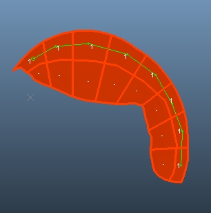
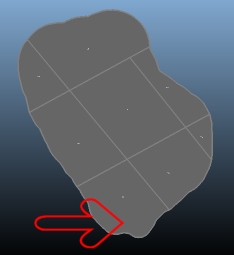
You can see the selection order as a batch of arrows by checking Selection order then selecting your blocks you wish to
edit. For example, the pink directional line below indicates order of selection: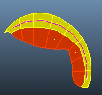
Selection Settings
Attributes can be applied to selected data only. You make your selection before using Apply to selected at the bottom of the screen.
The Selection area is used to choose the blocks to which you wish to assign attributes.
Note: Only visible blocks can be edited.
The first row of buttons (Select) are direct actions. They immediately select and highlight displayed data.
-
All – Select all blocks in view. Applying a static attribute will apply the attribute value to all blocks on display.
-
None – Deselect all blocks. A good way to clear the view and start again.
-
Invert – Toggle the selection status of blocks. This could be useful if you wish to define sequential attributes for multiple subsets of blocks on display.
The second row of buttons (Select using) are more interactive, meaning they rely either on mouse clicking, or the presence of other data:
-
Block solids – Enter block selection mode. In this mode, you can use the mouse to select any block that is displayed, noting that the selection order is important if you wish to apply sequential attributes (see below).
-
String segments – If a control string is displayed, you can pick the string edges to select blocks that are 'underneath' the string. All blocks that coincide (visually) with the selected string edges will either be assigned a static value, or a sequential value that is governed by the ordering of the string segments.
-
String vertices – Similar to the above, but this time, blocks are selected according to the location of the string vertices (points). Sequential attribution will also honor the vertex index for the selected string.
Note: Regardless of the selection method, all blocks in the line of view are updated.
You can also reverse the ordering of block selection (in effect, reverse the selected control string). To do this, select the blocks first, then click Reverse.
Note: The total number of
blocks for the current phase is shown in the "x out of
x blocks selected" message.
Using "Order By"
Only available if the Sequence option is selected, the following settings determine how a sequence of numbers is applied to your blocks:
| Selection order | A sequence is applied to blocks based on their selection order. This order can be set using any of the available options (manually or using a control string). |
| Distance from point |
Allows a sequence to be generated based on increasing distance from a reference point. The point is set by defining X and Y coordinates or picking a point interactively in the Task window If an interval is specified (it is optional) blocks are ordered according to the circle they fall within,
where the radius is applied to the origin point selected above.
By default, radii are projected in increments of 1 measurement
unit. By increasing this value, you create a radius 'band', within
which all block centroids that occur will be assigned the same
attribute value.
|
| Direction along azimuth |
Sequence mining blocks in a bench along a direction specified by an Azimuth and save the sequence numbers in a specified attribute. By default, each block is assigned a unique, incremental value. An Interval is required for this option; all blocks lie within the same distance 'band' as each other will have the same value (see Interval, below). If this option is selected, you can also choose the Path used to assign attributes:
|
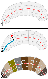
| Centerline |
In this case, the centreline of the mining blocks is used to determine the sequence attribute value, for example:
|

Interactive Attribution
The Interactive panel is used to apply a static or sequential attribute value to selected mining blocks.
The general procedure for interactive attribute assignment is:
- Define an attribute for your blocks, using the Attributes screen.
- Display the Interactive screen.
- Define your Display options by checking or unchecking them:
- Solids – Show mining block solids. Enabled by default.
- Outlines – Show mining block outlines.
- Attributes – Show attribute labels for mining blocks.
- Selection Order – Show the current selection order of blocks.
-
Select a Pit and Phase containing the mining blocks to be amended (filtering out everything else), or supply a custom filter by checking Other.
Tip: You can also filter using the Bench Clipping toolbar.
- Select the block(s) to be attributed. There are multiple methods for doing this:
- Select blocks in the order interactively
- Select string segments (normally, block outlines)
- Select string vertices
- Select the attribute to be assigned (as defined using the Attributes screen), and the value to be applied, either Fixed (across all blocks) or Sequence (in an increasing numerical sequence of a specific interval size.
- Apply the attribute to the blocks. You can do this either by specifying the attribute value to be applied or;
- by defining a numeric sequence based on either the block selection order or;
- the distance from a specific screen point (there's an example of this below), or;
- the position of blocks found in a direction of a given Azimuth value, or;
- selecting a centreline that passes through the blocks - attributes are assigned according to string direction.
- The Task window updates to show the newly-applied attribute as labels on each qualifying block.
- Save or Save and Close your task to update the mining blocks data file.
Attribution using a Control String
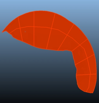
In the example below, the plan is to select a batch of 8 trim blocks on an upper phase so that a PFLAG attribute value of "1" can be applied to all selected blocks.
This will allow scheduling of these trim blocks to be managed using a specific set of scheduling activities later on. In this example, a digitized string will be used to control how attribute values are injected into the blocks.
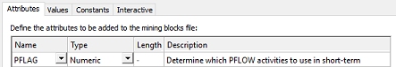
-
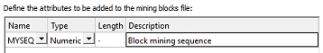
First, create an attribute (using the Attributes screen), for example:
- Display the Interactive screen.
- Display the Solids and Outlines for the bench blocks to be modified.
- Select the Pit and Phase relating to the blocks to be sequenced (or choose a custom filter using Other).
- Use the Bench Clipping toolbar to Filter Using Benches (in this example, using Above=0, Below=1).
-
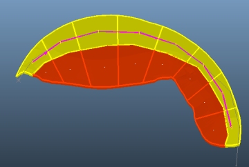
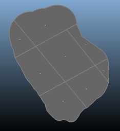
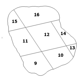
In this example, 8 trim blocks exist around the upper arch of the bench:
-
Digitize a string in the Task window so that a string point exists in each block, like this:
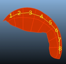
- Click Done.
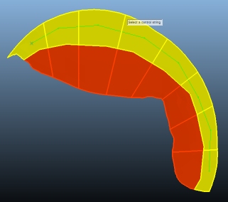
- Back on the Interactive screen, Selection group, choose Select using: String vertices.
-
Select the new string. All affected blocks are highlighted:
- In the Attribute group, make sure the attribute you wish to apply (such as PFLAG) is selected using Name.
- Select Fixed and enter "1" into the editable field (yo will applyy the same value to all blocks).
- Click Apply to Selected Blocks
- Up in the Display group, check Attributes to display attribute labels:
- Save your project
Sequential Attribution
You can also define a numeric sequence of values based on either your block selection order, or (as above) a control string. In the following example, a series of bench blocks will be sequenced according to the centre of each block from a digitized point indicating the block's initial access point.
-
First, create a numeric attribute (using the Attributes screen), such as:
- Display the Interactive screen.
-
Display the solids and outlines for the bench blocks to be modified. In this example, a set of 8 blocks were generated previously, for example:
- To store an incremental sequence in a new attribute (MYSEQ, in this example). It needs to be selected as the Attribute below.
-
Rather than set a fixed value, you're going to create a sequence, starting at 1 and increasing to 8. Each block is assigned a number based on its distance from the block entry point.
Select Sequence and use the following settings for the number sequence:

- Use Order by to select Distance from point.
- Using the pick button (that has just appeared) to digitize an origin point. In this case, it's here:
- You're going to sequence all visible blocks, so in the Selection area, click Select: All. This highlights all blocks in the current phase.
-
At the bottom of the panel, click Apply to selected.
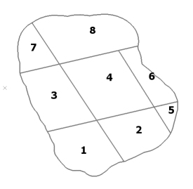
A numeric sequence is applied to each block as shown:
-
Check Continue to continue from the previous sequence number generated for any block within the block solids file. This is useful, for example, if you want to sequence blocks within one phase, then continue the number sequence in a subsequent phase.
For example, if you check Continue and reselect all of the same blocks as in the example above, then reapply the sequencing, you end up with this:
Related topics and activities: